Rotork Wiring Diagram Selector English 中文 Dutch Français Deutsch Italiano 日本語 한국어 Polski Русский Español Home;Read Or Download The Diagram Pictures Wiring For FREE Wiring Diagram at CROWDFUNDINGPLEDGEDEMOAGRIYACOMAftermarket TP100 Ignition Module of High Quality built by Dicktator with high qulaity electronic IGFET components These Modules have no internal electronic rev limiter such as the VW TP100 Modules and are compatible with any engine management system, aftermarket or standard(for eg Bosch MP9) Reference DKTP100 No customer reviews for the moment Product Query or
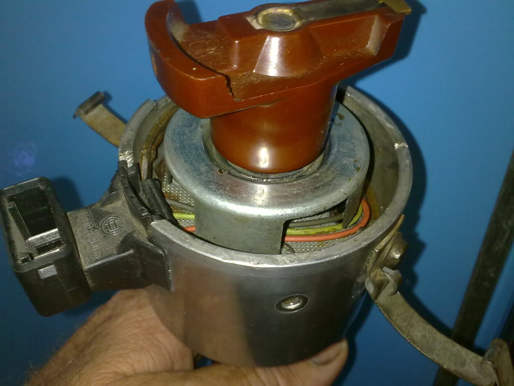
Convert To Electronic Ign Page 2 Aircooled Vw South Africa
Tp 100 module wiring diagram
Tp 100 module wiring diagram-About Us COVID19 Statement Our Purpose, Vision & Values Our Communities Our Markets Our Brands Our History Rotork plc Board Rotork Management Board Company Certificates Terms and ConditionsBond wires also add resistance to total loop impedance as well as connection integrity issues depending on the bond wire size and type of bond applied The loop resistance for the design used here was very low, less than 10 milliohms to the modules connection points and less than 25 milliohms when incorporated into some sort of control electronics and lead frame The total loop


Volvo S80 Wiring Diagram Pdf Download Manualslib
Complete protection of AUMA pottype motors is only achieved when correctly wiring the thermoswitches, embedded in the winding (plugs/terminals 19 and ) Microswitches ATTENTION !You should follow the wiring diagram ensuring you place the single white wire (for 3 wire) on one side of the circuit and the two red wires on the other The output will normally only have two terminals as a 4mA device will almost certainly be loop powered In other words, the 2 wires connected to the output provide the power supply in but also carry the mA signal out · Ignition Module Circuit Descriptions The ignition control module has two connectors Looking down at the ignition module (with the ignition module still bolted in place), you'll notice that the ignition control module has a left connector and a right connector In the pin out charts below is a brief job description of what each wire does
· Description Jem Wiring Diagram – Facbooik in Esp Ltd Wiring Diagrams, image size 990 X 767 px, and to view image details please click the image Published by simply admin in June, 3 15 If you like this article you can bookmark or share it to your social media account, I thanks significantly because you have visited this websiteTP 1000/2 AFABAQELX1 Product No EAN number Price Quotation Curves Performance Export Motor Settings Show advanced options Drawings Dimensional Drawing Wiring Diagram 3D Loading Show 3D 3D Top Left Front Right Bottom Back Close Download CAD/BIM drawings Select all Download Select the required CAD formats byWiring Diagram What is a Wiring Diagram?
· TP 100 module wiring Search Advanced search 6 posts • Page 1 of 1 16V Dub Cadet Posts 216 Joined Tue Apr 29, 08 732 am Car Make VW Car Model GOLF 1 Location Durban TP 100 module wiring Post by 16V Dub » Mon Jan 25, 10 648 pm Hwzt guys My set up is lt 16valve , side drafts I need some help with my module wiring I'm not getting spark from coil wireTp100 module wiring with pictures Thanks for the great advise guys ill have a look asap Use a wiring Bmw 6 cylinder diagram Afx airfuel monitor manual Mazda 2l fe wiring diagram My tps is a 8 pin plug with number 6 not used my coils are 3 pin Installation manual for the afx airfuel monitor Opel ecotec wiring diagramSingle Phase 5 Module Metal Clad 100A Fused Switch;


6ly2a Stp Wiring Diagram Page 4 Line 17qq Com


Ustec Residential Structured Wiring User Manual Model Number Installed By Pdf Free Download
Cable Management USBeautiful USB Sockets WiFi Range Extender Sockets Smart Sockets Support Back Technical Support UK Technical Support (Mon Fri 00 1600) 44 (0)3300125A 2 Pole Enclosed Switch Fuse (IP65) DC SwitchDisconnectors DC 4 Pole Enclosed Switchdisconnectors (IP65) Metal Clad DC 4 Pole Enclosed Switchdisconnectors with Fixing Brackets (IP55) Metal Clad DC 4 Pole Enclosed Switchdisconnectors with Fixing Brackets and MC4 Connectors (IP55) MC4Tp 100 module wiring diagram / tp 100 wiring diagram Tp 100 Wiring Diagram Oleh Anya Tanaya Januari 24, Posting Komentar Ignition Modules Diesel Electric Dicktator 60 2 Wiring Diagram Wiring Schematic Diagram All About Lipo Balance Connectors Tjintech Tp 10 C30 S40 V50 C70 Supplement Wiring Diagram Engineering Building Tentang Fire Alarm
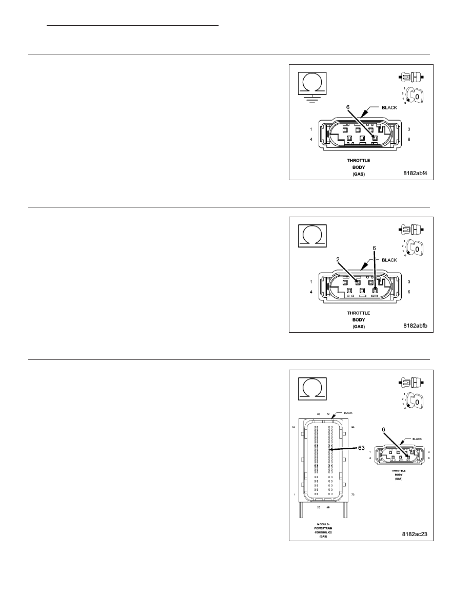


Dodge Caliber Manual Part 730


Edgerfid Remote Module With Rfid Function User Manual Kp 8in 1rel Tp 8in 1rel Tr 2in 1rel Gsi Electronics
TYPICAL INSTALLATION – MODEL TP2 The TP2 senses the electical power input to a motor (horsepower) The Output is a 4 Milliamp LOOP POWERED analog signal proportional to power 505 368HP 755 552HP 1005 736HP 1505 110HP 05 147HP 3005 221HP 4005 294HP 5005 368HP 7/07The TP 100 wood chipper is designed for stationary wood chipping in the form of braches etc The machine must not be used for materials containing stone, metal or other foreign b odies TheseTP E5ZF IS5100Z Series ZeroTurn Riding Mower Briggs & Stratton Yard Power Products Group 5375 North Main Street Munnsville, NY OPERATOR'S MANUAL Models Description 33HP Caterpillar Diesel w/ ROPS (IS5100Z/C33D) 33HP Caterpillar Diesel w/ ROPS Export (IS5100Z/C33DCE) 33HP Caterpillar Diesel w/
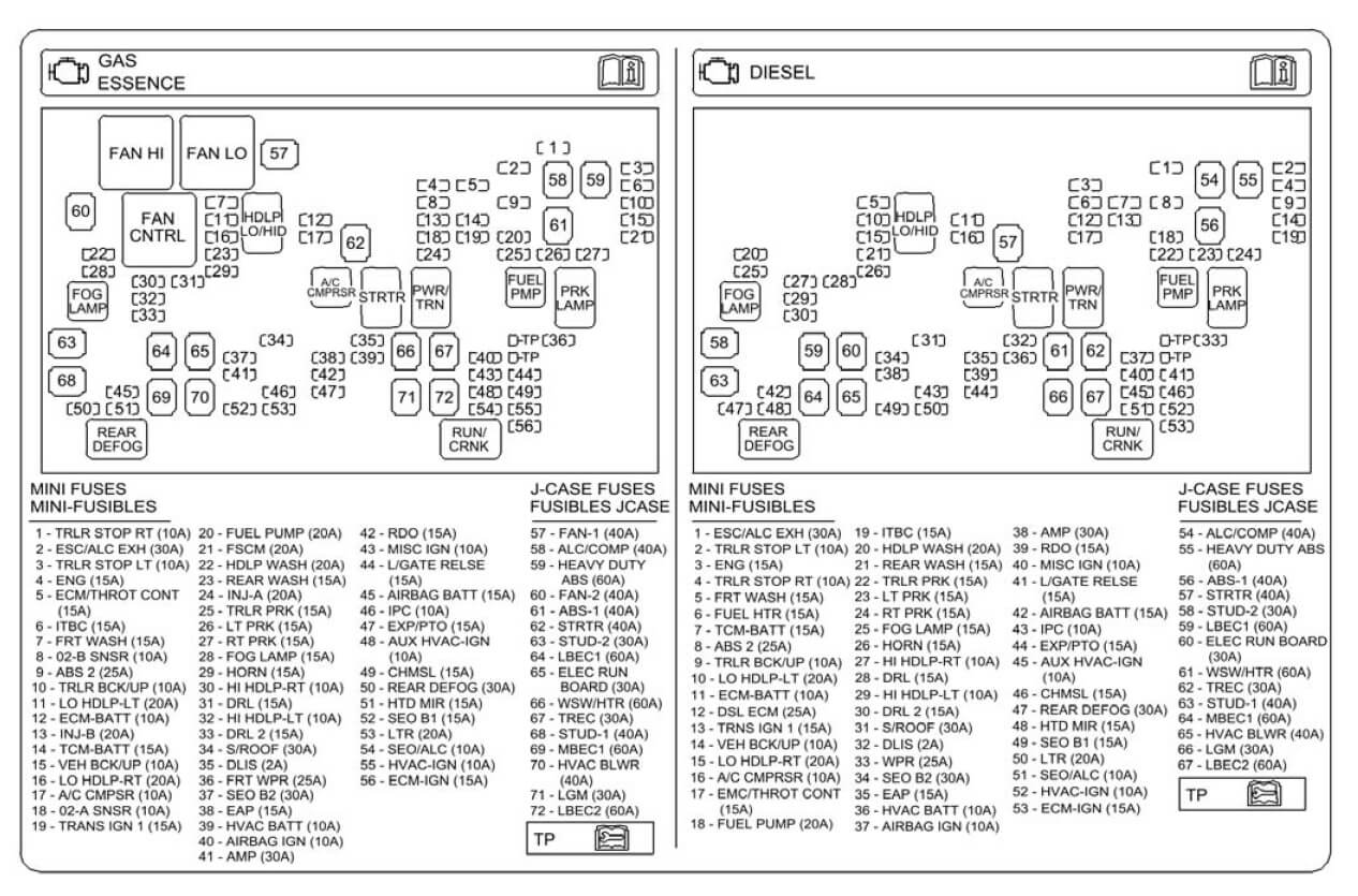


07 Tahoe Fuse Diagram Database Wiring Win Note Text Note Text Bologna Ristrutturazioni It


Datasheet By Phoenix Contact Digi Key Electronics
· 12way (Row) SPN = 12 X 1SP= 12Nos (Module) of single pole MCB as outgoing feeders Normally single phase distribution is mainly used for small single phase loads at house wiring or industrial lighting wiring 2) TPN Distribution Board (Incoming, Outgoing) 4way (Row) TPN = 4 X TP= 4nos of 3pole MCB as outgoing feeders =12 No of single pole MCB21module unit for larger installations and also a 4module unit to cater for small oneoff installations and extensions to existing ones The MK Electric Design Service offers a preassembly service for custom built boards with all devices fitted, busbars cut and fitted with devices, live and neutral cables terminated This service is available across the entire range of Metal, InsulatedTP ZF Briggs & Stratton Yard Power Products Group 5375 North Main Street Munnsville, NY IS3100Z Series ZeroTurn Riding Mower Model Number Description IS3100ZLKAV2661, 26HP, 61" Cut ZeroTurn Riding Mower IS3100ZK3061, 30HP, 61" Cut ZeroTurn Riding Mower IS3100ZBV3261, 32HP, 61" Cut


Mfi Instructional Manual Version Pdf Free Download


Amazon Com Cable Matters Ethernet Cable Share Kit Up To 100 Mbps Check The Connection Diagram Before Purchasing This Is Not A Two Pack Must Be Used In A Pair Computers
· Demi kebutuhan anda aku group the pictures vw tp100 wiring diagram 19 on the labels Tp wiring diagram hostrhdhjjrkoreichmediade dictator my diagramrh7qrafoutdoorjojode ignition module diagramsrhzcskaercherjskde wouter7s page the retro society of reverse engineering and taking rhretrocoza gerber ignition module wiring ford truck One side is formCeiling & Lighting Accessories; · Apollo 65 Wiring Diagram– wiring diagram is a simplified satisfactory pictorial representation of an electrical circuitIt shows the components of the circuit as simplified shapes, and the skill and signal connections amid the devices A wiring diagram usually gives guidance not quite the relative slant and deal of devices and terminals on the devices, to encourage in building
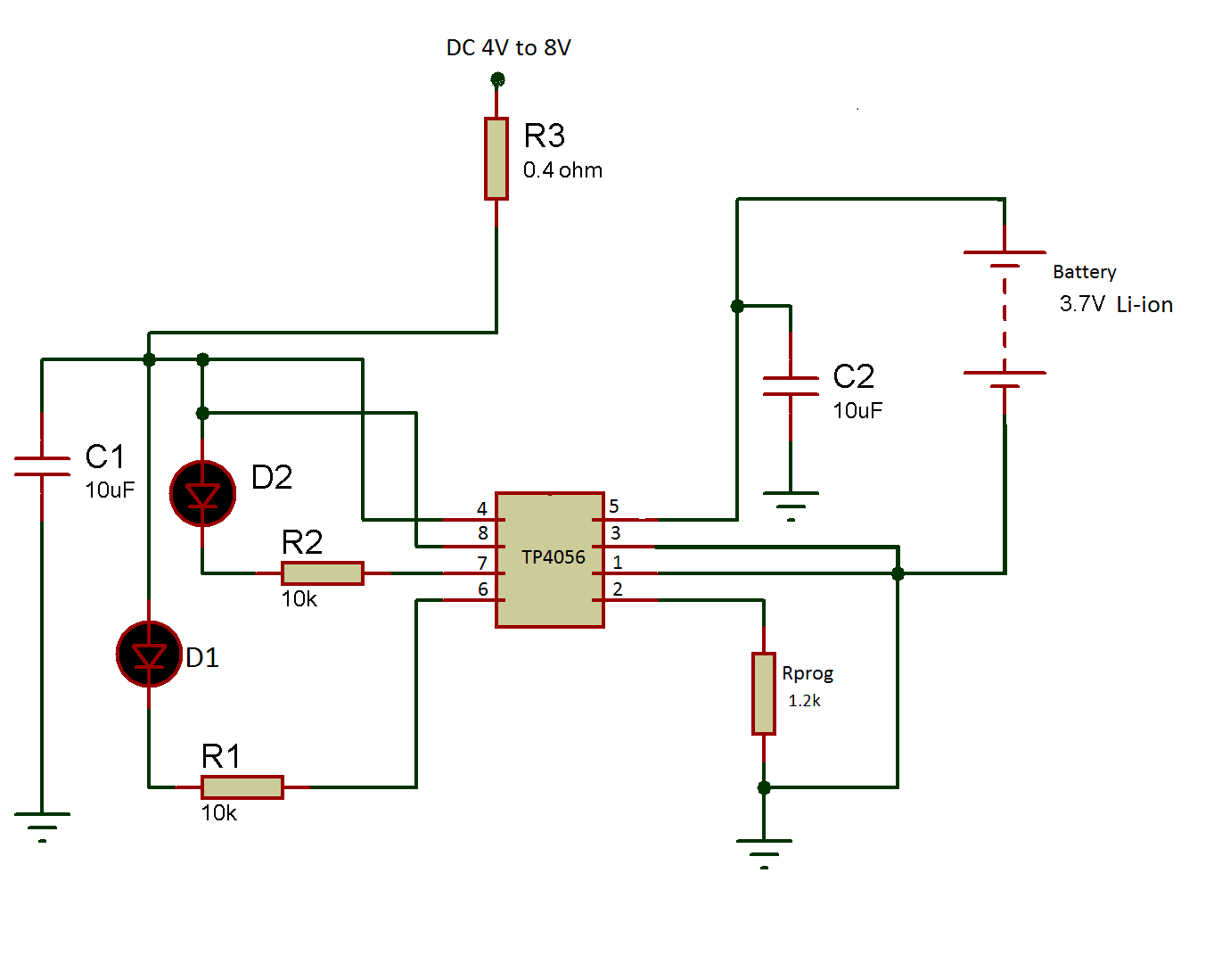


Make A 3 7 V Li Ion Battery Charger Using Tp 4056 Part 9 9
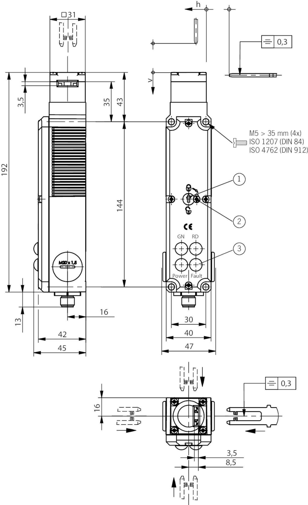


Tp3 4141a024sem4as1 Safety Switch Tp As1 Plug Connector M12 Closed Circuit Current Principle Euchner More Than Safety
How to Test an Ignition Control Module Remove one plug wire at the spark plug and insert an old spark plug into the end of the plug boot Check for voltage at the coil positive terminal when the ignition key is on Locate the ignition module positive () wire Locate the ignition module negative () wire · I need help with the wiring for the TP100 with the harness, I dnt want to burn the module or anything else Three wires , one red, one blue and one green and white that has an eye terminal on it Correct me if I am wrong here Red will go to the positive of the coil, blue will go the negative and the green&white wire ????Tp100 Wiring Diagram efcaviation design tp100 wiring diagram phptp wiring diagram diagrams facbooik with template 7 diagram diagrams tarako citroen berlingo radio mulliveemasin mysoda tp frog ee wiring gotech pain the volkswagen club of south africa afabqqe coil mashups bosch ignition module electronic ford Tp100 Wiring Diagram dk tp100


Tp900 Module Wiring Diagram Auto Electrical Wiring Diagram


Volvo V70 Xc70 S80 08 Electrical Wiring Diagram Manual Instant Download By Heydownloads Issuu
Home / Engine Management Systems / TP100 Ignition Module TP100 Ignition Module R TP100 Ignition Module quantity Add to cart SKU 094 Category Engine Management Systems Product ID 1678 Reviews (0) Reviews There are no reviews yet Be the · Then divide those resistances by half since there's two wires and we just want the resistance of one wire The final result is 102 1 1 = 100 Ω 3Wire RTDs These are very similar to the 4wire type but there is only one 'pair' of connected wires The reasoning for this is that the wires for the RTD are all pretty much the same gauge and length, so rather than having two pairs,A wiring diagram is a simple visual representation of the physical connections and physical layout of an electrical system or circuit It shows how the electrical wires are interconnected and can also show where fixtures and components may be connected to the system When and How to Use a Wiring Diagram


Diagram Database Free Read Or Download Diagram Database


Dicktator Connection Diagrams September 09 Ignition System Fuel Injection
There are 2 wiring methods for the RTD module and PT100 temperature sensors — twowire and threewire connections When wiring with two wires, first jumper across A1 and B1and and B2 respectively, then connect PT100 sensors and to the RTD module according to the following diagram on the left (Note A1B1, B2 and C1C2Order today, ships today HF100/24TP 100 – Flat Ribbon Cable Blue, White 24 (12 Pair Twisted) Conductors 0050" (127mm) Flat Twisted Pair 250' (762m) from 3M Pricing and Availability on millions of electronic components from DigiKey ElectronicsT – Thermal switch in motor;


Amazon Com Durablow Fireplace Electronic Ipi Pilot Ignition Control Module Replaces Dexen 593 592 Gm 6ka Hearth Home Technologies Hht 350 M Home Kitchen


Check Out This 1997 Bmw 318i Download Car Wiring Manuals فيسبوك
3phase 230 or 400 VAC Wiring diagram MPS1110KS3 F18E1 / KMS TP 100/001 egra con ro 1phase 230 VAC Wiring diagram MPS1130KC3 F18E1 / KMS(1) TP100/001 Explosionproof protection Yes, on request / Please, consult us Electric 3phase 400 VAC 50 Hz Electric actuator type Actuator output speed Nominal power Nominal intensity Starting intensity sec/90° kW A A 8 · TP designation for the diagram Protection according to the IEC standard TP 111 (slow overload) In order to handle a lockedrotor, the motor has to be fitted with an overload relay Automatic reclosing (left) and manual reclosing (right) Where S1 – On/off switch;The measurement between wire A and wire B will be over 100 ohms 17 The measurement between wire A and wire C will be the same 18 The measurement between wire B and wire C will be low, just the resistance of the wire itself 19 You will now have identified which wire is which Now connect them to the appropriate terminals on the controller So the marking on the


Datasheet By Phoenix Contact Digi Key Electronics


最も共有された Tp 100 Wiring Diagram
MV – Overload relay;Circuit Protection Back Fortress Circuit Protection;S2 – Off switch;


Pin On 150cc Scooter


Temperzone Service Training Manual
TPE /4 AFABQQELD3 = Wiring Diagram Spare parts 3D Loading Show 3D Top Left Front Right Bottom Back Download CAD drawings Spare parts Parts list Collapse Expand Clear Curve settings Show advanced options × Modal title Cancel OK Specifications;3 wire pt100 wiring diagram welcome to my site this message will discuss concerning 3 wire pt100 wiring diagram This digital photography of vw tp100 wiring diagram mp9 21 images diagrams is the best ideas that we have chosen from thousands of designs available on the internet Wiring there are 2 wiring methods for the rtd module and pt100 temperature sensors two wire and three wirePage 35 Wiring Diagrams 7 Wiring Diagrams 71 Indoor Unit Code No DBA Samsung Electronics Page 36 72 Outdoor Unit SH24TP6(A)X / UQT24P6GE DIAGRAMOUTDOOR Code No DBA UQT24P6GB DIAGRAMOUTDOOR Code No


Power Esp32 Esp66 With Solar Panels And Battery Random Nerd Tutorials


Volvo S80 Wiring Diagram Pdf Download Manualslib
· A further possibility to substantially decrease the influence of the cabling is to increase the conductor crosssection With a crosssection of 05 mm 2 the line resistance is only 0036 Ω/m or 01 °C/m Both options (3/4wire connection or increasing the crosssection) lead to a higher cost in the cabling, which can be problematic, especially in costsensitive markets suchOnly the same potential can be switched on the two circuits of a microswitch If different potentials are to be switched simultaneously, the use of tandem switches imposes (two galvanically · Straight through LAN cables are the most common, and the pinout is the same if they are Cat5e, Cat6, or Cat 7 The different types of cables (category or cat) offer increasingly faster transmit and receive speeds This is achieved by increasing the wire twists, better shielding, drain wire, and increased wire diameter


Edgerfid Remote Module With Rfid Function User Manual Kp 8in 1rel Tp 8in 1rel Tr 2in 1rel Gsi Electronics


Kteb 2c72 1 Tp Keystone Electronic Fluorescent Ballast
· Assortment of rtd pt100 3 wire wiring diagram A wiring diagram is a streamlined standard photographic depiction of an electrical circuit It shows the components of the circuit as streamlined shapes, and also the power and also signal links between the gadgets · The most common type PT100 has a resistance of 100Ω at 0°C and 1384 ohms at 100°C RTDs come in 2wire, 3wire or 4wire versions The 2wire RTD signal is affected by the distance to the controller, but 3wire or 4wire RTDs can compensate for line losses Unlike thermocouples, special connection cables are not very necessary for PT100 sensors However,Videos (0) Documents (0) CAD drawings;


Edgerfid Remote Module With Rfid Function User Manual Kp 8in 1rel Tp 8in 1rel Tr 2in 1rel Gsi Electronics


Tp100 Wiring Diagram Basic Car Wiring Diagram 1984 Cupe Simple Starter Rccar Wiring Nescafe Jeanjaures37 Fr
Tp 100 Wiring Diagram picture put up and uploaded by Admin that kept inside our collection I need help with the wiring for the tp100 with the harness i dnt want to burn the module or anything else Wiring diagram pictures detail Tp100 Wiring Diagram Today Wiring Schematic Diagram Tp 100 Wiring Diagram have an image from the otherTp wiring diagram hostrhdhjjrkoreichmediade dictator my diagramrh7qrafoutdoorjojode ignition module diagramsrhzcskaercherjskde wouter7s page the retro society of reverse engineering and taking rhretrocoza gerber ignition module wiring ford truck One side is form the ignition and the otherside is from either the tp100 or the points depending on how old the mk1 is Wiring there are 2 wiringTechnical manuals offering installation directions, wiring diagrams and troubleshooting advice 4810N Series GSM Intercom 4810N Series GSM Intercom – Firmware version 102 – 108 4000 Series GSM Lite Intercom 4000 Series GSM Lite Audiokits – LTGSM4K / LTGSM4KC 4802 Series Digital GSM Intercom 4802 Series Digital GSM – Firmware version 102 – 4 380N/UK


South Africa S Most Trusted Engine Management System Dicktator


Edgerfid Remote Module With Rfid Function User Manual Kp 8in 1rel Tp 8in 1rel Tr 2in 1rel Gsi Electronics
· I have been given a little project to do, but I am confused by this wiring diagram I have a PT100 sensor 4mA transmitter Digital Display (temperature) From the above circuit diagram, I see that the PT100 sensor will go in to terminals 7, 8, 9 The transmitter needs a 24vDC supply, and the digital display gets it signal from two wires from the transmitter The powerTp 100 Module Wiring Diagram Part 1 How To Test The 1 8l Vw Ignition Control Module And Ignition Coils Tp 10 C30 S40 V50 C70 Supplement Wiring Diagram Basicpindioderfswitch Controlcircuit Circuit Diagram Seekic Wiring Diagram Database Tp 100 Module Wiring Diagram のギャラリー Dicktator Tp100 Ignition Module Incl Plug Pins Controller Bacnet Ms Tp 750 9Page 31 Q'TY Remark PCB MODULE FR1 T16 CONNECTORHEADER BOX, 3P, 1R, 2mm, ANGLE, SN CCERAMIC, MLCAXIAL 1nF, 10%, 50V, Y5P, TP, 19x35, DIODESWITCHING 1N4148, 100V, 0mA, DO35, TP CCERAMIC, MLCAXIAL 100nF, 80%, 50V, Y5V, TP, 35x1 MODULE FRP4021H7 Samsung Electronics Page 32 Wiring Diagram 8 Wiring Diagram 81 Indoor Unit


5 0dpn4 4ovbnm


Mfi Instructional Manual Version Pdf Free Download
Except for the 2wire configuration, all other wiring arrangements allow the monitoring or control equipment to factor out the unwanted lead wire resistance and other resistances that occur in the circuit Sensors using the 3wire construction are the most common design, found in industrial process and monitoring applications The lead wire resistance is factored out as long as all of theMotor module (drive motor impeller terminal box/ electronics module) for exchange in the TOP Series PLR Pump master computer, Wilospecific data bus Pt 1000 Platinum temperature sensor with a resistance value of 1,000 Ω at 0 °C Q (= ) Delivery rate SBM Process signal or collective run signal SSM Collective fault signal V Abbreviation Meaning Control input "010 V" Analog inputTL1 TP 100XX All Top Connections Minimum space requirements for access and servicing Top 1685 mm (To allow for Htype flushing by pass), Front 700 mm, Side 50 mm, Bottom 50 mm
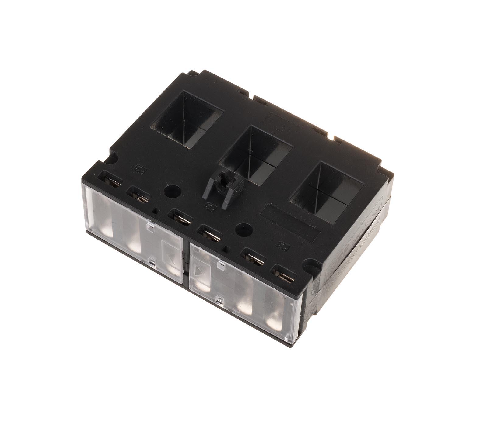


Current Transformer Tp 100
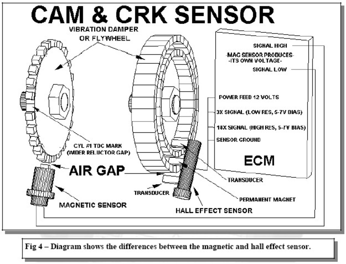


Engine Control Module And Sensor Locations Axleaddict


Rcl Rr8 Tp Rc Logger R8 Radio System User Manual Cei Conrad Electronic Hk


Amazon Com Cable Matters Ethernet Cable Share Kit Up To 100 Mbps Check The Connection Diagram Before Purchasing This Is Not A Two Pack Must Be Used In A Pair Computers


Smart Light Switch Wiring Problem Page 1 Line 17qq Com


South Africa S Most Trusted Engine Management System Dicktator
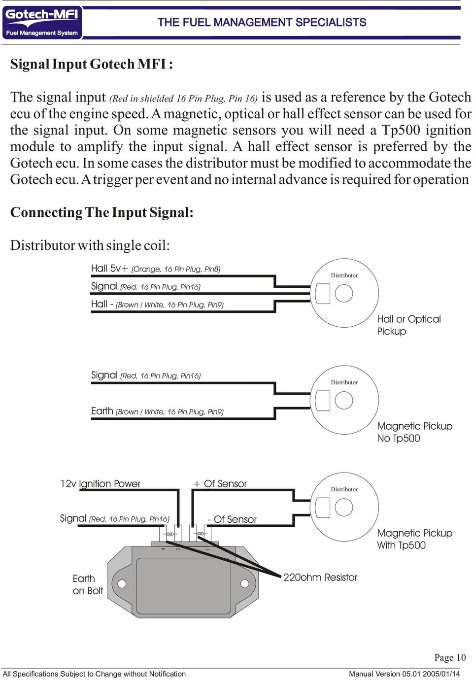


Mfi Instructional Manual Version Pdf Free Download


Sea Ray Electrical Wiring Diagram Page 1 Line 17qq Com


South Africa S Most Trusted Engine Management System Dicktator


How To Install Dmo565r Smps Ic Module In Led Tv Crt Tv Str Dmo565r Circuit Diagram Youtube


Tp900 Module Wiring Diagram Auto Electrical Wiring Diagram


Tp100 Ignition Module Dicktator


Tp100 Wiring Diagram Humbucker Wiring Diagrams 2 Vol 1 Tone M Au Delice Limousin Fr


Tuya Smart Life Wifi Curtain Blind Switch For Roller Shutter Electric Motor Google Home Alexa Echo Voice Control Diy Smart Home


Edgerfid Remote Module With Rfid Function User Manual Kp 8in 1rel Tp 8in 1rel Tr 2in 1rel Gsi Electronics


07 Tahoe Fuse Diagram Database Wiring Win Note Text Note Text Bologna Ristrutturazioni It


Convert To Electronic Ign Page 2 Aircooled Vw South Africa
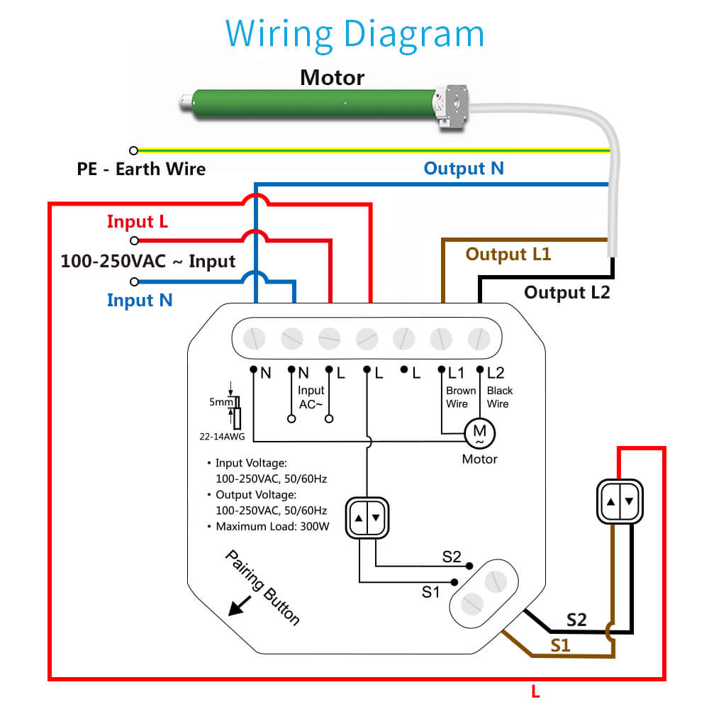


Tuya Smart Life Wifi Curtain Blind Switch For Roller Shutter Electric Motor Google Home Alexa Echo Voice Control Diy Smart Home


Jeep Grand Cherokee Wk Manual Part 0


Installation Directions
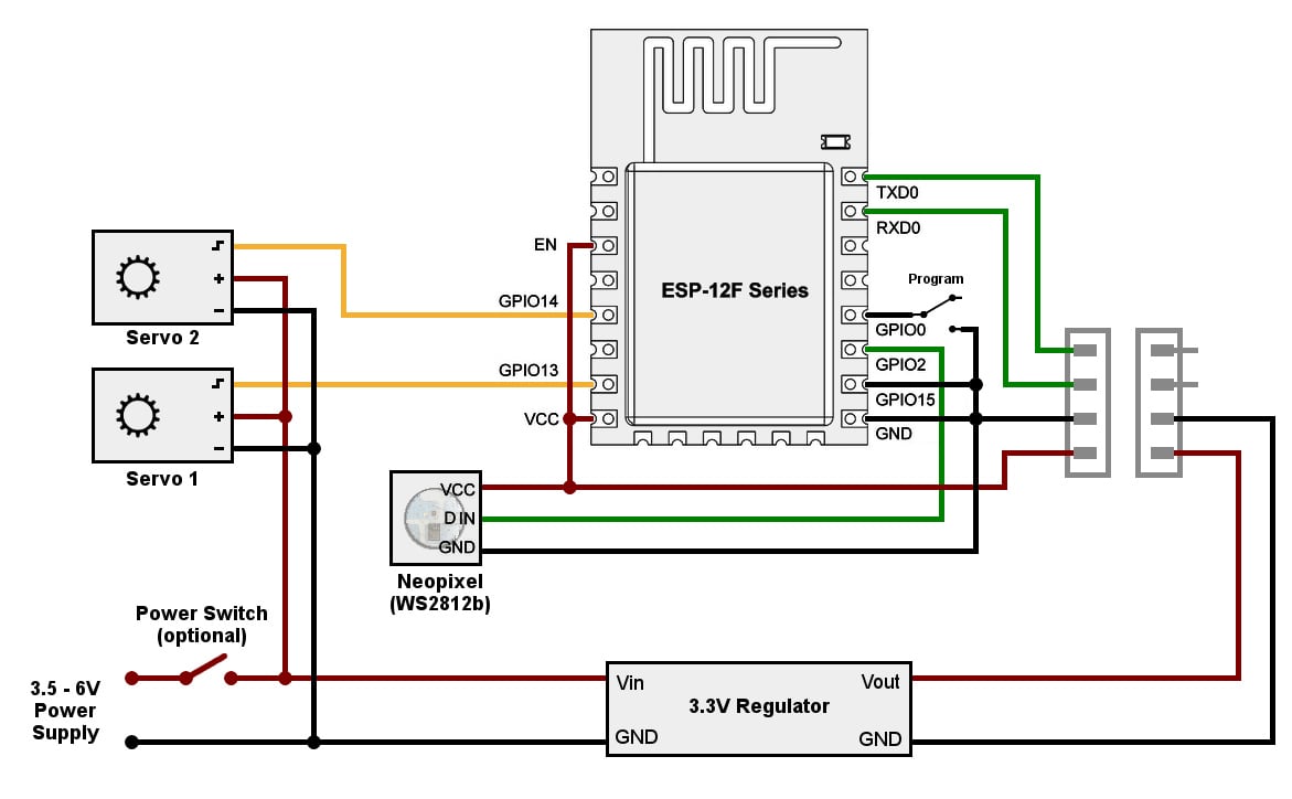


Diagram Venstar Wi Fi Wiring Diagram Full Version Hd Quality Wiring Diagram Outletdiagram Villalarco It
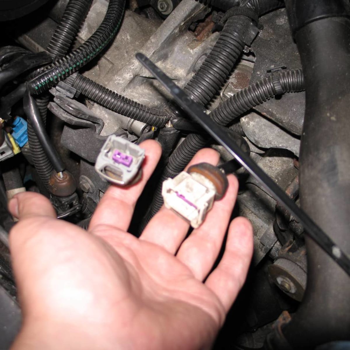


How Do You Know If A Throttle Position Sensor Is Bad Axleaddict
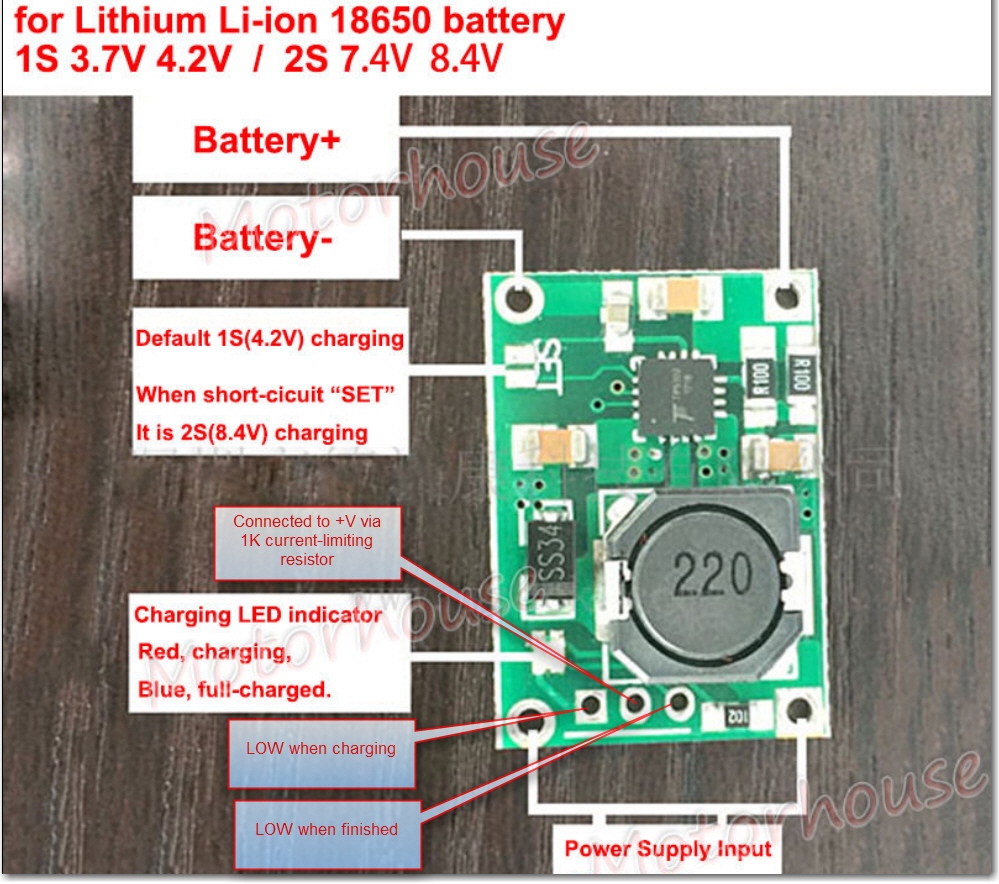


Tp5100 2 Cell Lipo Charger Module Study Paynter S Palace


Volvo Xc90 13 Electrical Wiring Diagram Manual Instant Download Pdf By Heydownloads Issuu
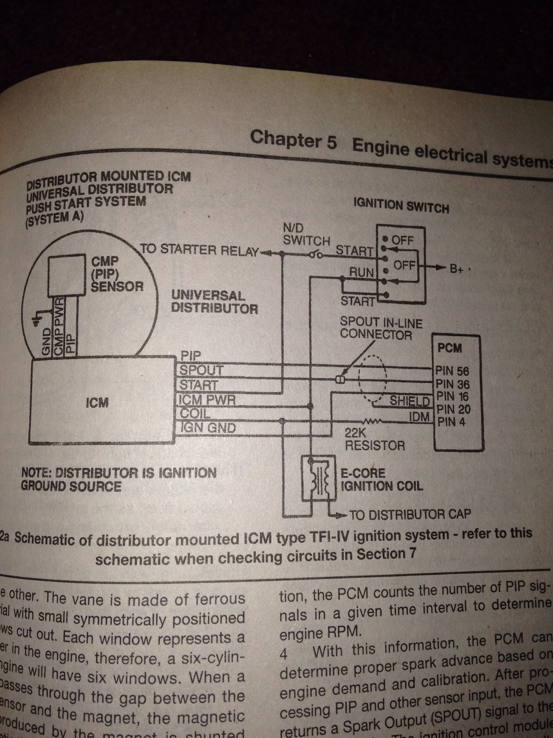


No Power To The Ignition Control Module Ford Truck Enthusiasts Forums


Edgerfid Remote Module With Rfid Function User Manual Kp 8in 1rel Tp 8in 1rel Tr 2in 1rel Gsi Electronics


Tp100 Wiring Diagram Basic Car Wiring Diagram 1984 Cupe Simple Starter Rccar Wiring Nescafe Jeanjaures37 Fr


Mfi Instructional Manual Version Pdf Free Download


Tp900 Module Wiring Diagram Auto Electrical Wiring Diagram


3 Way Touch Sensor Dimmer Touch Lamp Repair Kit Control Module Replacement Sensor Touch Switch 150watt Amazon Com


Zing Ear Tp 01 Zh Touch Lamp Light Dimmer Switch Control Sensor Amazon Com


Suzuki Swift Wiring Diagram Diagrams Throughout Electrical Diagram Electrical Wiring Diagram Repair Guide


Tp900 Module Wiring Diagram Auto Electrical Wiring Diagram


Rdt Cfnc 0100a Owner S Manual Manualzz


Lincoln Electric Invertec Cc400 T Operator S Manual Pdf Download Manualslib
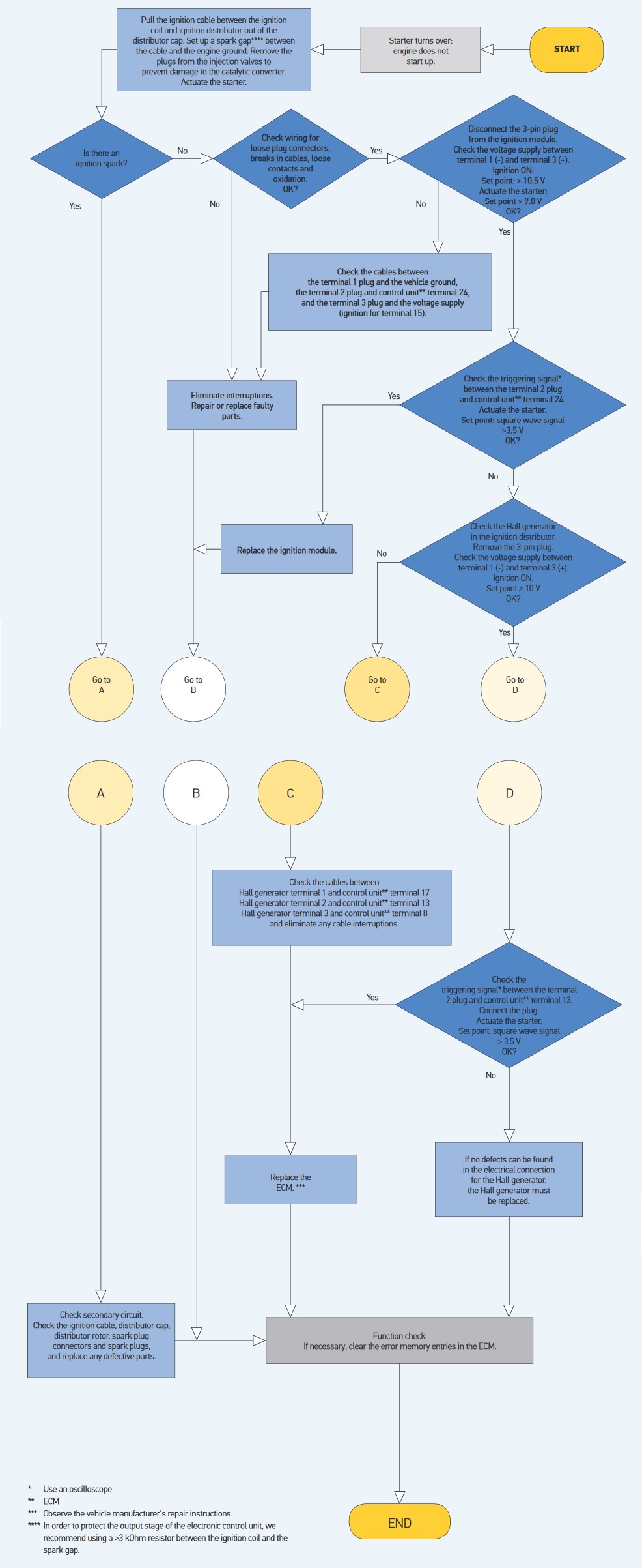


Ignition Coil Checking Measuring Faults Hella


Diagram Database Free Read Or Download Diagram Database
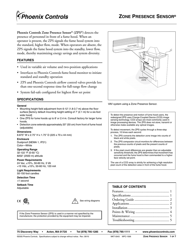


Zone Presence Sensor Manualzz


Diagram 97 F150 Overdrive Wiring Diagram Full Version Hd Quality Wiring Diagram Beefdiagram Firenzefiesolemusei It


I Believe The Thing I Need Is A Wiring Diagram For A 1998 Olds 3800 Series It Has A No Spark Condition It Does Have


Kteb 2 1 Tp Emi Keystone Ballast


0 件のコメント:
コメントを投稿